Youyi YY-D-200-5-PFC-K Series 5V 40A 100~240V LED Power Supply
Electrical Specification
Input Electrical Characteristics
| Project | YY-D-200-5 K Series |
|
Normal output power |
200W |
|
Normal voltage range |
100 Vac ~240Vac |
| Input voltage range | 88 Vac ~264Vac |
|
Frequency range |
47HZ~63HZ |
|
PF |
≥0.95 |
|
Leakage Current |
≤0.25ma,@220Vac |
|
Max input AC current |
3A |
|
Inrush current |
Cold boot 45A(Test at 50% Ipeak: twidth=600us)/230VAC |
| Efficiency(full load) | 90% (@220V) |

Output Electrical Characteristics
Operate temperature rating Curve

If the product has long been working at the environment - 40℃, please indicate your special request.
Output current and voltage curve
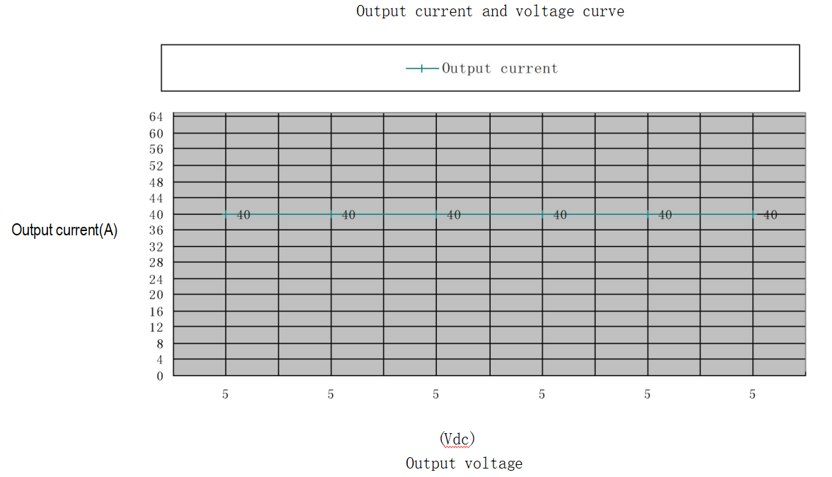
Output Voltage And Current Regulation
|
Project |
YY-D-200-5 K Series |
|
Output Voltage |
5.0V |
|
Setting Accuracy (No load) |
±0.1V |
|
Output Rated Current |
30A(INPUT:100Vac -175Vac); 40A(INPUT:176Vac -240Vac)
|
|
Peak Current |
32A(INPUT:100Vac -175Vac); 41A(INPUT:176Vac -240Vac) |
|
Regulation |
±3% |
Power on Delay Time
|
Delay Time |
220Vac Input @ -40~-5℃ |
220Vac Input @ ≥25℃ |
|
Output Voltage:5.0 Vdc |
≤5S |
≤3S |
|
Output Voltage:5.0 Vdc |
≤6S |
≤3S |
Output Transient Response
|
Output Voltage |
Change Rate |
Voltage Range | Load Change |
| 5.0 Vdc |
1~1.5A/uS |
≤±5% |
@Min.to 50% load and 50% to max load |
|
5.0Vdc |
0.5~1A/uS |
≥±3% |
DC Output Voltage Rise Time
|
Output Voltage |
220Vac input & full load |
Note |
| 5.0 Vdc | ≤50mS | The rise time measured is when the output voltages rise from 10% to 90% of specified output voltage Vout observed on the channel waveform. |
| 5.0Vdc | ≤75mS |
DC Output Ripple & Noise
|
Output Voltage |
Ripple & Noise |
| 5.0 Vdc |
150mVp-p@25℃ |
|
240mVp-p@-25℃ |
Measure Methods
A. Ripple & Noise test:Ripple & Noise bandwidth is set to 20mHZ.
B. Use a 0.1uf ceramic capacitor in parallel with a 10uf electrolytic capacitor at output connector terminals for ripple & noise measurements.
Protection Function
Output Short Circuit Protection
|
Output Voltage |
Comments |
|
5.0 Vdc |
Output will be stopped when the circuit is shorted and restart operating after eliminating malfunction. |
Output Over Load Protection
|
Output Voltage |
Comments |
| 5.0 Vdc | Output will stop working when the output current is more than 105~138% of rated current and it will restart working after eliminating malfunction. |
Over Temperature Protection
|
Output Voltage |
Comments |
| 5.0 Vdc |
Output will stop working when the temperature above the set value and it will restart working after eliminating malfunction. |
Isolation
Dielectric Strength
|
Input To Output |
50Hz 3000Vac Ac file test 1 minute,Leakage current≤5mA |
|
Input To FG |
50Hz 1500Vac Ac file test 1 minute,Leakage current≤5mA |
Insulation Resistance
|
Input To Output |
DC 500V The minimum insulation resistance must be no less than 10MΩ(at room temperature) |
|
Output To FG |
DC 500V The minimum insulation resistance must be no less than 10MΩ (at room temperature) |
|
Input To FG |
DC 500V The minimum insulation resistance must be no less than 10MΩ(at room temperature) |
EMC
Environment Requirement
Environment Temperature
Working Temperature:-25℃~+60℃
Storage Temperature:-40℃ ~ +70℃
Humidity
Working Humidity: Relative humidity is from 15RH to 90RH.
Storage Humidity: Relative humidity is from 10RH to 95RH.
Altitude
Working Altitude: 0 to 3000m
Shock & Vibration
A. Shock: 49m/s2(5G),11ms,once each X,Y and Z axis.
B. Vibration: 10-55Hz,19.6m/s2(2G),20 minutes each along X,Y and Z axis.
Cooling Method
Natural cooling
Specific Cautions
A. The product should be suspended in air or installed on the face of metal when it is assembled, and be avoided to place on the face of non-conducting heat materials such as, plastics, board and so on.
B. The space between each module should be exceeded 5cm in order to avoid affecting cooling of power supply.
MTBF
The MTBF shall be at least 50,000 hours at 25℃ at the condition of full loading.
Pin Connection
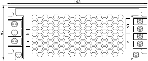
Unit:mm
Table 1 : Input 3 pin terminal block (pitch 9.5mm)
|
Name |
Function |
|
L |
The AC Input Line L |
|
N |
The AC Input Line N |
|
Earth Line |
Table 2 :Output 4 pin terminal block (pitch 8.25mm)
Current conducted through the output terminal block should not exceed 25A, so do not overload test and work at that condition. Or the terminal block will be damaged from high temperature.
|
Name |
Function |
|
V+ V+ |
Output DC positive pole |
|
V- V- |
Output DC negative pole |
Power Supply Mounting Dimension
Dimensions
Outside dimension : L*W*H=143×60×31mm
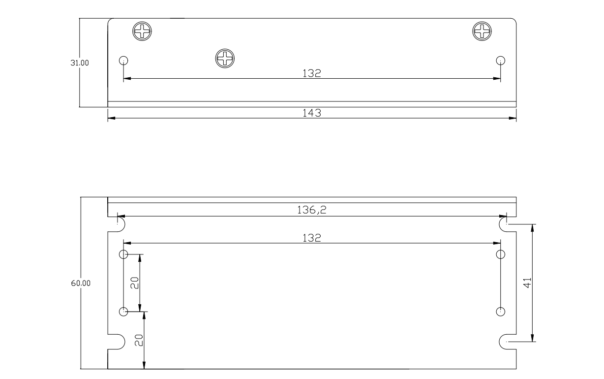
Unit:mm
Method 1: M3 screws lock in the mounting rack of 4 U grooves under the cabinet.
One way should be chosen from the two methods, make sure that the part of screw that is in the body of power supply should be less than 3mm and exert not much strength to avoid damaging the screw.
Precautions Of Use
The power supply must work at the condition of insulation and terminal post of cable have to go through the insulation treatment. Besides, make sure the product is grounded well and forbid touching the cabinet in order to avoid scalding hand.

.jpg)
-300x300.jpg)
-300x300.jpg)


