Novastar MRV336 LED Display Receiver Card
Introduction
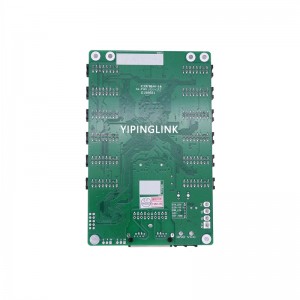
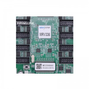
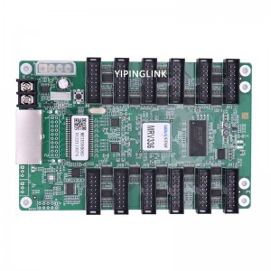
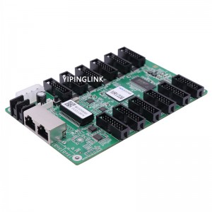
The MRV336 is a general receiving card developed by NovaStar. A single MRV336 loads up to 256×226 pixels. Supporting various functions such as pixel level brightness and chroma calibration, the MRV336 can greatly improve the display effect and user experience.
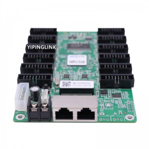
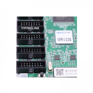
The MRV336 uses 12 standard HUB75E connectors for communication, resulting in high stability. It supports up to 24 groups of parallel RGB data. Thanks to its EMC Class B compliant hardware design, the MRV336 has improved electromagnetic compatibility and is suitable to various on-site setups.
Features
⬤Support for 1/32 scan
⬤Pixel level brightness and chroma calibration
⬤Support for setting of a pre-stored image in receiving card
⬤Configuration parameter readback
⬤Temperature monitoring
⬤Ethernet cable communication status monitoring
⬤Power supply voltage monitoring
Appearance
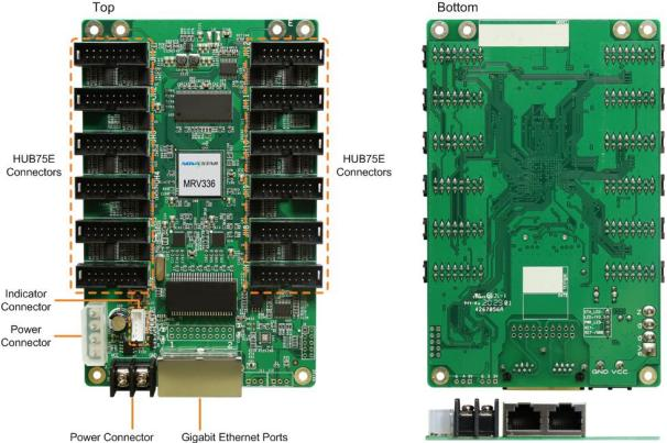
All product pictures shown in this document are for illustration purpose only. Actual product may vary.
| Pin Definitions of the Indicator Connector (J9) | ||||
| 1 | 2 | 3 | 4 | 5 |
| STA_LED | LED +/3.3V | PWR_LED- | KEY+ | KEY-/GND |
Indicators
| Indicator | Color | Status | Description |
| Running indicator | Green | Flashing once every 1s | The receiving card is functioning normally. Ethernet cable connection is normal, and video source input is available. |
| Flashing once every 3s | Ethernet cable connection is abnormal. | ||
| Flashing 3 times every 0.5s | Ethernet cable connection is normal, but no video source input is available. | ||
| Flashing once every 0.2s | The receiving card failed to load the program in the application area and is now using the backup program. | ||
| Flashing 8 times every 0.5s | A redundancy switchover occurred on the Ethernet port and the loop backup has taken effect. | ||
| Power indicator | Red | Always on | The power supply is normal. |
Dimensions
The board thickness is not greater than 2.0 mm, and the total thickness (board thickness + thickness of components on the top and bottom sides) is not greater than 19.0 mm. Ground connection (GND) is enabled for mounting holes.
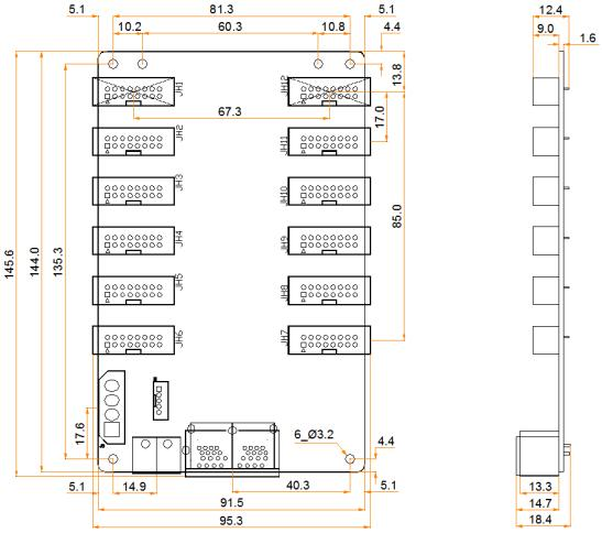
Tolerance: ±0.1 Unit: mm
Pins
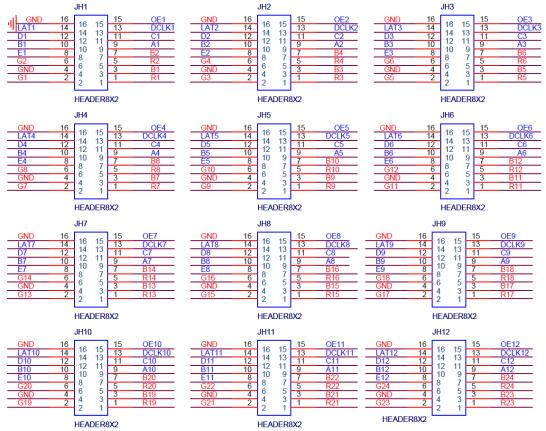
| Pin Definitions | |||||
| / | R | 1 | 2 | G | / |
| / | B | 3 | 4 | GND | Ground |
| / | R | 5 | 6 | G | / |
| / | B | 7 | 8 | E | Line decoding signal |
| Line decoding signal | A | 9 | 10 | B | |
| C | 11 | 12 | D | ||
| Shift clock | DCLK | 13 | 14 | LAT | Latch signal |
| Display enable signal | OE | 15 | 16 | GND | Ground |
Specifications
| Maximum Loading Capacity | 256 × 226 pixels | ||
| Electrical
Specifications |
Input voltage | DC 3.3 V to 5.5 V | |
| Rated current | 0.5 A | ||
| Rated power
consumption |
2.5 W | ||
| Operating
Environment |
Temperature | –20°C to +70°C | |
| Humidity | 10% RH to 90% RH, non-condensing | ||
| Storage | Temperature | –25°C to +125°C | |
| Environment | Humidity | 0% RH to 95% RH, non-condensing | |
| Physical
Specifications |
Dimensions | 145.6 mm × 95.3 mm × 18.4 mm | |
| Packing
Information |
Packing specifications | An antistatic bag and anti-collision foam are provided for each receiving card. Each packing box contains 100 receiving cards. | |
| Packing box dimensions | 650.0 mm × 500.0 mm × 200.0 mm | ||
| Certifications | RoHS, EMC Class B | ||
The amount of current and power consumption may vary depending on factors such as product settings, usage, and environment.


