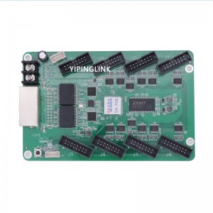
Novastar A5S Plus Receiver Card LED Display HUB320 HUB210 HUB75E HUB Board HUB Adapter Plate For Nova AxS Series Receiver


HUB75E
.png)
.png)
.png)
HUB210
.png)
.png)
.png)
.png)
HUB320
.png)
.png)
.png)
.png)
A5s PLUS Introduction
The A5s Plus is a general small receiving card developed by Xi’an NovaStar Tech Co., Ltd. (hereinafter referred to as NovaStar). For PWM driver ICs, a single A5s Plus supports resolutions up to 512×384@60Hz. For common driver ICs,a single A5s Plus supports resolutions up to 384×384@60Hz. Supporting color management, 18bit+, pixel level brightness and chroma calibration, quick seam correction, low latency, 3D, individual gamma adjustment for RGB, image rotation in 90°increments, and other functions, the A5s Plus can significantly improve the display effect and user experience.
The A5s Plus uses high-density connectors for communication to limit the effects of dust and vibration, resulting in high stability. It supports up to 32 groups of parallel RGB data or 64 groups of serial data (expandable to 128 groups of serial data). Its reserved pins allow for custom functions of users. Thanks to its EMC Class B compliant hardware design, the A5s Plus has improved electromagnetic compatibility and is suitable for various on-site setups.
A5s PLUS Features
Improvements to Display Effect
⬤Color management
Support the standard color gamuts (Rec.709, DCI-P3 and Rec.2020) and custom color gamuts, enabling more precise colors on the screen.
⬤18bit+
Improve the LED display grayscale by 4 times to avoid grayscale loss due to low brightness and allow for a smoother image.
⬤Pixel level brightness and chroma calibration
Work with NovaStar’s high-precision calibration system to calibrate the brightness and chroma of each pixel, effectively removing brightness differences and chroma differences, and enabling high brightness consistency and chroma consistency.
⬤Quick adjustment of dark or bright lines
The dark or bright lines caused by splicing of cabinets or modules can be adjusted to improve the visual experience. This function is easy to use and the adjustment takes effect immediately.
In NovaLCT V5.2.0 or later, the adjustment can be performed without using or changing the video source.
⬤Low latency
For PWM driver ICs, the latency of video source on the receiving card end can be reduced to 1 frame. For DCLK continuous PWM driver ICs, to use low latency, the customized firmware is required.
⬤3D
Working with the controller that supports 3D function, the receiving card supports 3D image output.
⬤Individual gamma adjustment for RGB
Working with NovaLCT (V5.2.0 or later) and the controller that supports this function, the receiving card supports individual adjustment of red gamma, green gamma and blue gamma, which can effectively control image non-uniformity at low grayscale conditions and white balance offset, allowing for a more realistic image.
⬤90°image rotation
The display image can be rotated in multiples of 90°(0°/90°/180°/270°).
Improvements to Maintainability
⬤Smart module (dedicated firmware required)
Working with the smart module, the receiving card supports module ID management, storage of calibration coefficients and module parameters, monitoring of module temperature, voltage and flat cable communication status, LED error detection, and recording of the module run time.
⬤Automatic module calibration
After a new module with flash memory is installed to replace the old one, the calibration coefficients stored in the flash memory can be automatically uploaded to the receiving card when it is powered on, ensuring high consistency for both display brightness and chroma.
⬤Quick uploading of calibration coefficients
The calibration coefficients can be quickly uploaded to the receiving card, improving efficiency greatly.
⬤Module Flash management
For modules with flash memory, the information stored in the memory can be managed. The calibration coefficients and module ID can be stored and read back.
⬤One click to apply calibration coefficients in module Flash
For modules with flash memory, when the Ethernet cable is disconnected, users can hold down the self-test button on the cabinet to upload the calibration coefficients in the flash memory of the module to the receiving card.
⬤Mapping 1.0
The cabinets display the receiving card number and Ethernet port information, allowing users to easily obtain the locations and connection topology of receiving cards.
⬤Setting of a pre-stored image in receiving card
The image displayed during startup, or displayed when the Ethernet cable is disconnected or there is no video signal can be customized.
⬤Temperature and voltage monitoring
The temperature and voltage of the receiving card can be monitored without using peripherals.
⬤Cabinet LCD
The LCD module connected to the cabinet can display the temperature, voltage, single run time and total run time of the receiving card.
⬤Bit error detection
The Ethernet port communication quality of the receiving card can be monitored and the number of erroneous packets can be recorded to help troubleshoot network communication problems.
⬤Status detection of dual power supplies
When two power supplies are used, their working status can be detected by the receiving card.
⬤Firmware program readback
The firmware program of the receiving card can be read back and saved to the local computer.
⬤Configuration parameter readback
The configuration parameters of the receiving card can be read back and saved to the local computer.
Improvements to Reliability
⬤Dual card backup and status monitoring
In an application with requirements for high reliability, two receiving cards can be mounted onto a single hub board for backup. When the primary receiving card fails, the backup card can serve immediately to ensure uninterrupted operation of the display.
The working status of the primary and backup receiving cards can be monitored in NovaLCT V5.2.0 or later.
⬤Loop backup
The receiving cards and the controller form a loop via the primary and backup line connections. When a fault occurs at a location of the lines, the screen can still display the image normally.
⬤Dual backup of configuration parameters
The receiving card configuration parameters are stored in the application area and factory area of the receiving card at the same time. Users usually use the configuration parameters in the application area. If necessary, users can restore the configuration parameters in the factory area to the application area.
⬤Dual program backup
Two copies of firmware program are stored in the receiving card at the factory to avoid the problem that the receiving card may get stuck abnormally during program update.
A5s PLUS Appearance
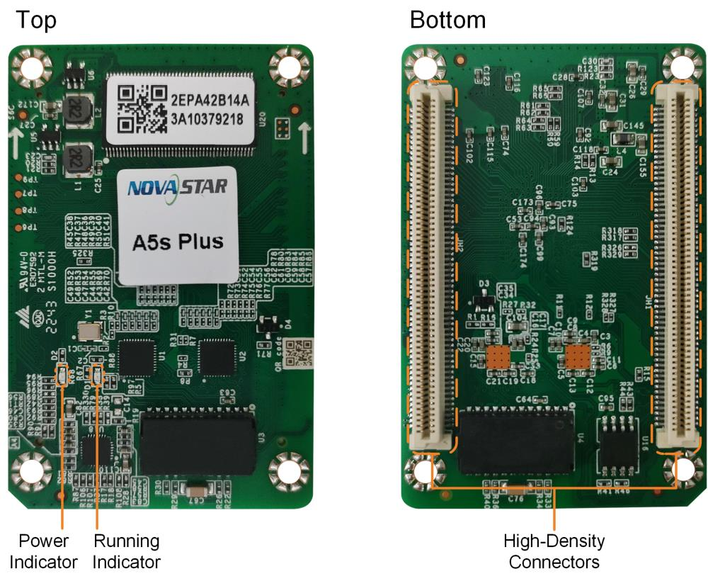
A5s PLUS Indicators
| Indicator | Color | Status | Description |
| Running
indicator |
Green | Flashing once every 1s | The receiving card is functioning normally. Ethernet cable connection is normal, and video source input is available. |
| Flashing once every 3s | Ethernet cable connection is abnormal. | ||
| Flashing 3 times every 0.5s | Ethernet cable connection is normal, but no video source input is available. | ||
| Flashing once every 0.2s | The receiving card failed to load the program in the
application area and is now using the backup program. |
||
| Flashing 8 times every 0.5s | A redundancy switchover occurred on the Ethernet port and the loop backup has taken effect. | ||
| Power
indicator |
Red | Always on | The power input is normal. |
A5s PLUS Dimensions
The board thickness is not greater than 2.0 mm, and the total thickness (board thickness + thickness of components on the top and bottom sides) is not greater than 8.7 mm. Ground connection (GND) is enabled for mounting holes.
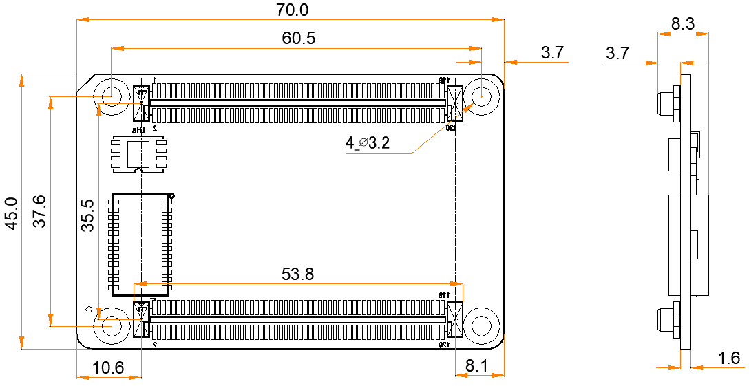
Note:
The distance between outer surfaces of the A5s Plus and hub boards after their high-density connectors fit together is 5.0 mm. A 5-mm copper pillar is recommended.
To make molds or trepan mounting holes, please contact NovaStar for a higher-precision structural drawing.
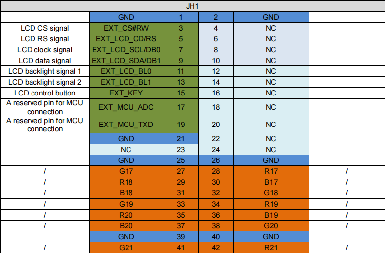
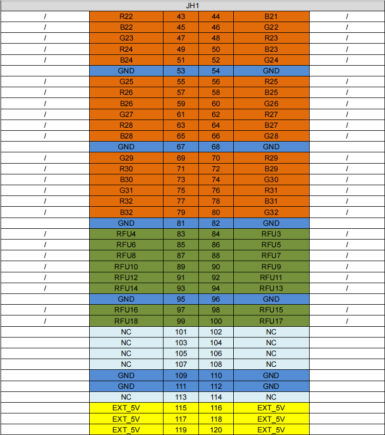
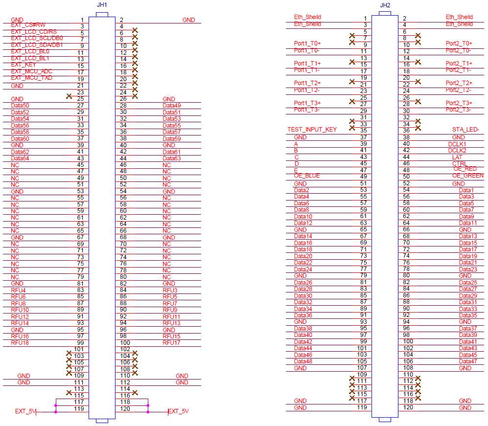
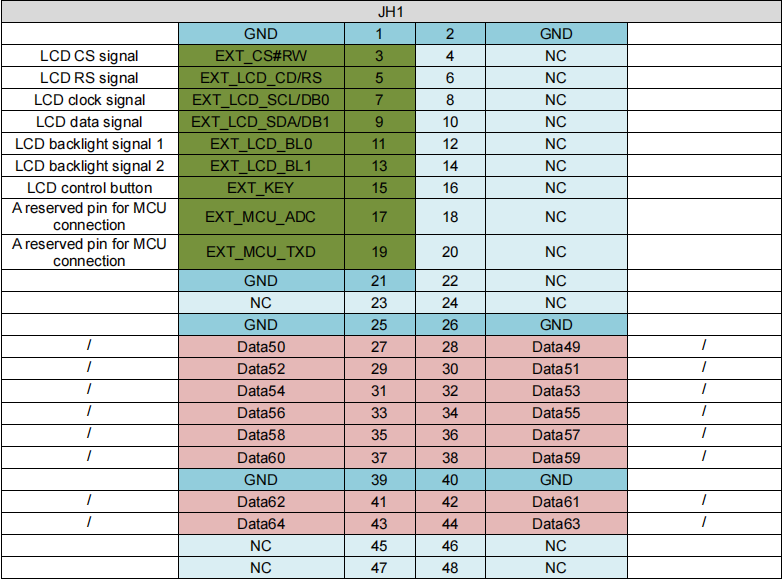
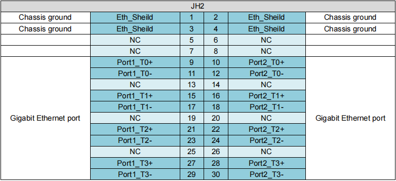
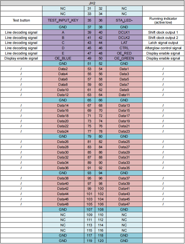
A5s PLUS PINS
32 Groups of Parallel RGB Data
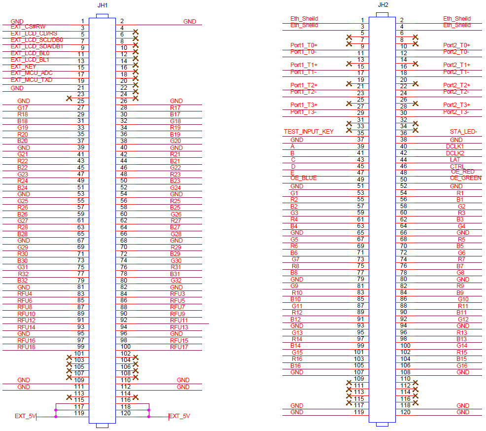
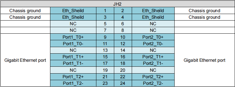
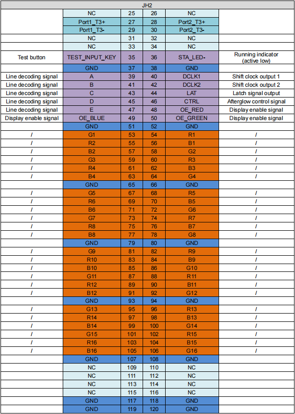
64 Groups of Serial Data
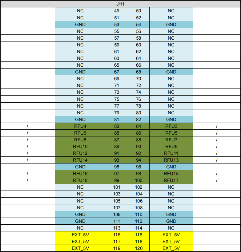
Note:
The recommended power input is 5.0 V.
OE_RED, OE_GREEN and OE_BLUE are display enable signals. When RGB are not controlled separately, use OE_RED. When the PWM chip is used, they are used as GCLK signals.
In the mode of 128 groups of serial data, Data65-Data128 are multiplexed into Data1-Data64.
Reference Design for Extended Functions
| Pins for Extended Functions | |||
| Pin | Recommended Module Flash Pin | Recommended
Smart Module Pin |
Description |
| RFU4 | HUB_SPI_CLK | Reserved | Clock signal of serial pin |
| RFU6 | HUB_SPI_CS | Reserved | CS signal of serial pin |
| RFU8 | HUB_SPI_MOSI | / | Module Flash data storage input |
| / | HUB_UART_TX | Smart module TX signal | |
| RFU10 | HUB_SPI_MISO | / | Module Flash data storage output |
| / | HUB_UART_RX | Smart module RX signal | |
| RFU3 | HUB_CODE0 |
Module Flash BUS control pin |
|
| RFU5 | HUB_CODE1 | ||
| RFU7 | HUB_CODE2 | ||
| RFU9 | HUB_CODE3 | ||
| RFU18 | HUB_CODE4 | ||
| RFU11 | HUB_H164_CSD | 74HC164 data signal | |
| RFU13 | HUB_H164_CLK | ||
| RFU14 | POWER_STA1 | Dual power supply detection signal | |
| RFU16 | POWER_STA2 | ||
| RFU15 | MS_DATA | Dual card backup connection signal | |
| RFU17 | MS_ID | Dual card backup identifier signal | |
Note:
The RFU8 and RFU10 are signal multiplex extension pins. Only one pin from either the Recommended Smart Module Pin or the Recommended Module Flash Pin can be selected at the same time.
A5s PLUS Specifications
| Maximum Resolution | 512×384@60Hz (PWM driver ICs)
384×384@60Hz (Common driver ICs) |
|
| Electrical Parameters | Input voltage | DC 3.8 V to 5.5 V |
| Rated current | 0.6 A | |
| Rated power consumption | 3.0 W | |
| Operating Environment | Temperature | -20°C to +70°C |
| Humidity | 10% RH to 90% RH, non-condensing | |
| Storage Environment | Temperature | -25°C to +125°C |
| Humidity | 0% RH to 95% RH, non-condensing | |
| Physical Specifications | Dimensions | 70.0 mm × 45.0 mm × 8.3 mm |
|
Net weight |
16.2 g
Note: It is the weight of a single receiving card only. |
|
| Packing Information | Packing specifications | Each receiving card is packaged in a blister pack. Each packing box contains 80 receiving cards. |
| Packing box dimensions | 392.0 mm × 200.0 mm × 123.0 mm | |
The amount of current and power consumption may vary depending on various factors such as product settings, usage, and environment.
-300x300.jpg)