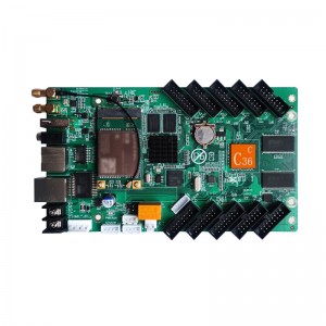
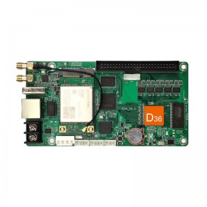
Huidu C36C USB WIFI Controller 1024*512 LED Display
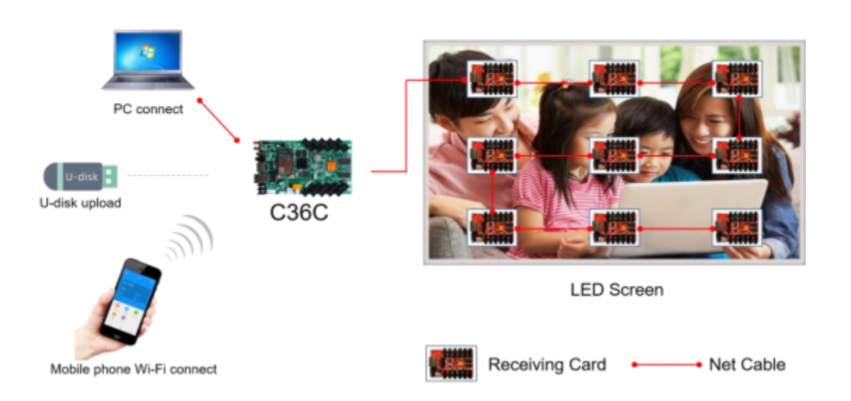
Controlling System Configuration
|
Product |
Type |
Functions |
|
Async controller Card |
HD-C36C |
Asynchronous core control panel, with storage capabilities, can be connected to,the screen modules, with 10 lines HUB75E port. |
|
Receiving Card |
R Series |
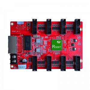
Connected with screen, Showing program in Screen. |
|
Control Software |
HDPlayer |
Screen parameters setting, edit & send program etc. |
Control Mode
Internet unified management: The play box can be connected to the Internet through 4G (optional), network cable connection, or Wi-Fi Bridge.

Asynchronous one-to-one control: Update programs by network cable connections, Wi-Fi connections or USB flash drives. LAN (cluster) control can access the LAN network through by network cable connection or Wi-Fi Bridge.
Product Features
● Control Range: 5204288 pixels (1024*512).
● 4GB memory, support expending memory by U-disk.
● Support HD video hardware decoding, 60Hz frame rate output.
●Support widest 8192 pixels, Highest 1024 pixels.
● No need set IP address, it could be identified by controller ID automatically.
● Unified management of more LED display through Internet or LAN.
● Equipped with Wi-Fi function, Mobile APP management directly.
●Equipped with 3.5mm standard audio interface output.
● Meanwhile support to add 4G networking module connect to Internet (Optional).
● Equipped with 10 lines HUB75E port, can be used for one receiving card.
● Equipped with 1 group of relay module, support switch on/off power supply directly remotely.
System Function List
|
Function |
Parameters |
|
Module type |
Compatible with indoor and outdoor full color and single color module Support conventional chip and mainstream PWM chip |
|
Scan Mode |
Static to 1/64 scan mode |
|
Control Range |
1024*512, widest 8192, highest 1024 |
|
Gray Scale |
256-65536 |
|
Basic functions |
Video, Pictures, Gif, Text, office, Clocks, Timing etc. Remote, Temperature, Humidity, Brightness etc. |
|
Video format |
Support,1080P,HD,video,hardware,decoding,direct transmission, without transcoding waiting,60Hzframe frequency output; AVI, WMV, MP4, 3GP, ASF, MPG, FLV, F4V, MKV, MOV, DAT, VOB, TRP, TS, WEBM, etc. |
|
Image Format |
Support BMP, GIF, JPG, PNG, PBM, PGM, PPM, XPM, XBM etc. |
|
Text |
Text editing, Image, Word, Txt, Rtf, Html etc. |
|
Document |
DOC, DOCX, XLSX, XLS, PPT, PPTX etc. Office2007Document format. |
|
Time |
Classic Analog clock, digital clock and of clock with image background. |
|
Audio output |
Double track stereo audio output. |
|
Memory |
4GB Flash memory; Indefinite expanding of U-disk memory. |
|
Communication |
Ethernet LAN port, 4G network (optional), Wi-Fi, USB. |
|
Working Temperature |
-20℃-80℃ |
|
Port |
INPUTS: 5V DC*1, 100 Mbps RJ45*1, USB 2.0*1, test button*1, sensor port*1, GPS port*1. OUT:1Gbps RJ45*1, AUDIO*1 |
|
Power |
8W |
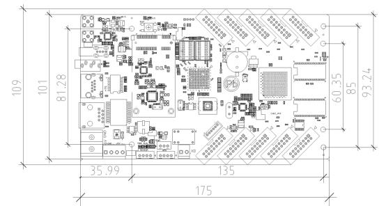
Dimension Chart
Appearance Description
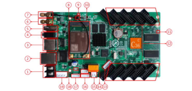
1. Power Supply port: connected 5V DC power supply.
2. Output network port: 1Gbps network port, connect to receiving card.
3. Input Network port: Connect to PC or router.
4. Audio output port: support standard two-track stereo output.
5. USB port: connected to USB device, e.g. U-disk, Mobile hard disk etc.
6. Wi-Fi antenna connection port: connect with external Wi-Fi antenna.
7. 4G network antenna connection port: connect with external 4G antenna (Optional) .
8. Test button: LED screenburn-intest
9. 4G indicator light: display 4G network status.
10. Mini PCIE port: connect with 4G networking module for cloud control (Optional).
11. Display indicator light: working status is Flicking.
12. HUB75E port: connect to LED modules with flat cable.
13. Reserved interface, no definition.
14. Temp sensor connection port: connect to temperature sensor and show the real-time value.
15. Relay control connection port: the power supply connection port of the relay
16. GPS port: connected GPS module.
17. Sensor port: connect S108 and S208 sensor kit.
18. Controller working state indicator light: PWR is Power lamp for status of power supply, when working normally, the lamp is always on, RUN is running lamp, when working normally, the lamp will be blinking.
19. Fool-proof power interface: 5V DC power interface, with fool-proof design, with the same function as the “1” 5V DC terminal.
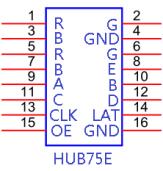
Interface Definition
Onboard 10 HUB75E port (2*8pin)
Basic Parameters
| Minimum | Typical | Maximum | |
| Rated voltage(V) | 4.2 | 5.0 | 5.5 |
| Storage temperature(℃) | -40 | 25 | 105 |
| Work environment temperature(℃) | -40 | 25 | 80 |
| Work environment humidity (%) | 0.0 | 30 | 95 |
| Net weight (kg) | 0.12 | ||
| Certificate | CE, FCC, RoHS | ||
Precaution
1) To ensure that the control card is stored during normal operation, make sure the battery on the control card is not loose,
2) In order to ensure the long-term stable operation of the system; please use the standard 5V power supply voltage.


